
Raspberry Pi RFID tag reader
This post explains how to add an RFID tag reader to your Raspberry Pi. You can read the unique ID numbers from RFID cards or tags and make things happen on your Raspberry Pi depending on which card is waved over.

To make the reader, we bought a couple of RDM6300 boards, two RFID tags and an RFID card. For the Pi, we used an old Pi Model B+ V1.2 and installed Jessie Lite on an SD card.
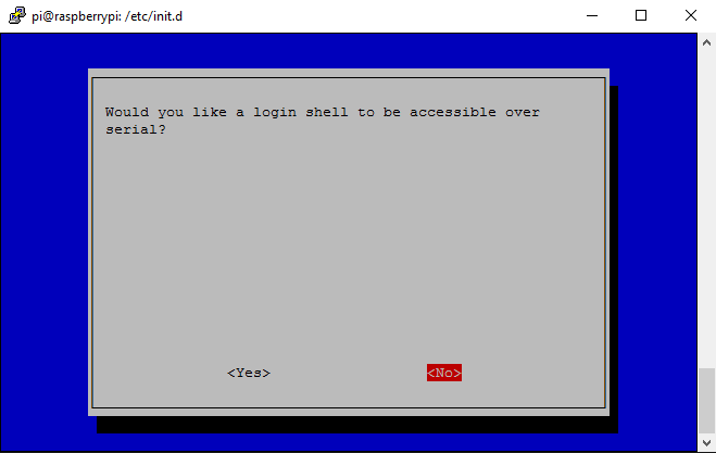
The RDM6300 is powered by 5V and communicates using UART with a 3.3V logic level. To start, we need to disable “login shell over serial” to release the serial pins of the Pi for our use.
Using Serial Pins on the Pi
- Power the Pi,
- Connect network and log on the Pi using SSH.
- Enter username and password.
- Enter the following command
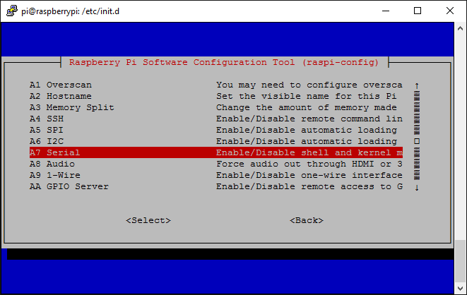
- Disable the serial at logon, as shown by the following screenshots.
sudo raspi-config
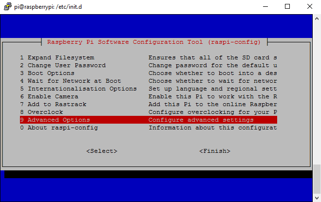
Reboot the Pi.
With the latest version of Jessie, the UART is disabled by default. To enable it, edit config.txt:
sudo nano /boot/config.txt
and add the line at the end of the file:
enable_uart=1
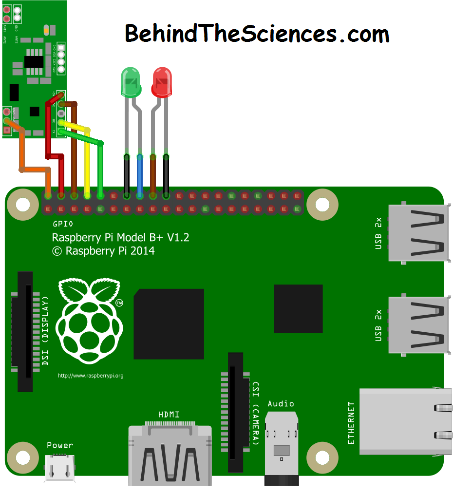
Connect the circuit according to the figure below, connect the antenna to the ant connector and power the Pi:
 To connect to the Pi over SSH, we used Putty.
Python should be installed by default but not python-serial; run the following command:
sudo apt-get install python-serial
Python Code
We wrote the following simple code and tried to read some tags.
import time
import serial
import RPi.GPIO as GPIO
GPIO.setmode(GPIO.BCM)
Tag1 = str('1800387799CE')
GPIO.setup(23,GPIO.OUT)
GPIO.setup(24,GPIO.OUT)
GPIO.output(23,False)
GPIO.output(24,False)
PortRF = serial.Serial('/dev/ttyAMA0',9600)
while True:
	ID = ""
	read_byte = PortRF.read()
	if read_byte=="\x02":
		for Counter in range(12):
			read_byte=PortRF.read()
			ID = ID + str(read_byte)
			print hex(ord( read_byte))
		print ID
		if ID == Tag1:
			print "matched"
			GPIO.output(23,True)
			GPIO.output(24,False)
			time.sleep(5)
			GPIO.output(23,False)
		else:
			GPIO.output(23,False)
			print "Access Denied"
			GPIO.output(24,True)
			time.sleep(5)
			GPIO.output(24,False)
Save the following code as RFID.py and then run it using:
python RFID.py
Wave a tag over the antenna and you will see readings coming up.
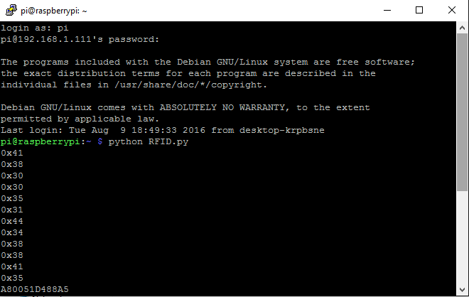
The tags we have are the EM4100 and the data from the tags is composed of a start flag, 12 bytes of data and a stop flag. The start flag is 0x02 and the stop flag is 0x03.
The python code open the UART and reads the RxD pin in a loop. When 0x02 is read, the code enters a loop that read the consecutive 12 bytes. The 12 bytes are then combined into a string called ID. The terminal shows the 12 bytes and the combined string at the end.
We have saved a tag ID as a string (Tag1). When a tag is waved over the antenna, the string of the read tag is compared with Tag1 and if it’s a match, the green LED turns on. The red LED turns on when it is not a match.
This code does not flush the serial buffer and can read the tag multiple times. Clearing the buffer after a successful read can be implemented at ease.
Please stay updated; next post will show how RFID can be used for door access control.
Contact us at [email protected]
Related Posts


About The Author
behindthesciences
We are two engineers who work in the Electronic and Telecommunication industry. We regularly blog in our spare time.
An underscore is missing in enable_uart=1
There is already an underscore in there. Not sure where you are suggesting another underscore should be. 😶
I followed all this tutorial but i can’t read anything from the serial. I opened a thread here https://raspberrypi.stackexchange.com/questions/78596/rpirdm6300-serial-port-not-working
i wanna know what python and pyserial, do you use in the code?
We don’t understand your question :/
Please re-phrase. 🙂
el codigo muestra error en python 3, usando la raspberry pi 3 B+, puedes ayudarnos con el error?
Sorry, we don’t understand. :/
Ah sorry, if you meant what version, then it’s python 2.7
In the diagram, the RDM6300 is powered using the Pi’s 5V (which is required), however, the RDM6300’s TX outputs 5V too, and is plugged directly in the Pi’s RX, which only accepts 3.3V. I am afraid this setup will damage the Pi.
Yes, it is connected UART is connected directly to the Pi. With previous test that we performed, we found out that when a GPIO was connected to 5V, the currents flowing are just way too small to cause any damage to the Pi.
However, on our commercial products, we always have logic shifters.
Kind regards,
The BehindTheSciences Team.
I have received several RDM6300 boards marked V2.0 from different sources which have an on board 3.3V regulator to power the microcontroller on the RDM6300 board. Looking at the TX output on these boards with a scope shows they output a 3.3 volt level signal. If you can confirm you have this revision of the board , there is no need for level translation or resistors to 3.3V devices such as the Pi
Thanks for your input Vikon Tech 🙂