
How to record the garage door openers signal
If you want to record your garage door opener signal in order to, for example, see the coded pulses you can do it with a RTL-SDR dongle. If you are thinking to get a dongle, you can read a review of the dongle I used here.
What you need
In order to follow this tutorial, you’d need:
- The RTL2838 dongle which you will connect to your PC through the USB port. In addition, you need to plug in the antenna to receive signals.
- The HDSDR software, which is free and very intuitive to use
- Matlab or other software which is able to read a .wav file and allow you to process it (Audacity can be a good open source alternative)
- A garage door opener which name and brand you can google in order to find some key characteristics. I used this one.

Step 1: research a bit about your remote
The goal here is to record the signal properly and know what to expect from it. After googling the name of my remote, I found it’s got the following features:
Transmission frequency: 433.92 MHz
Channels: 10
Code: fixed
Encoder: PT2264 (here you can check the Remote Control Encoder IC datasheet)
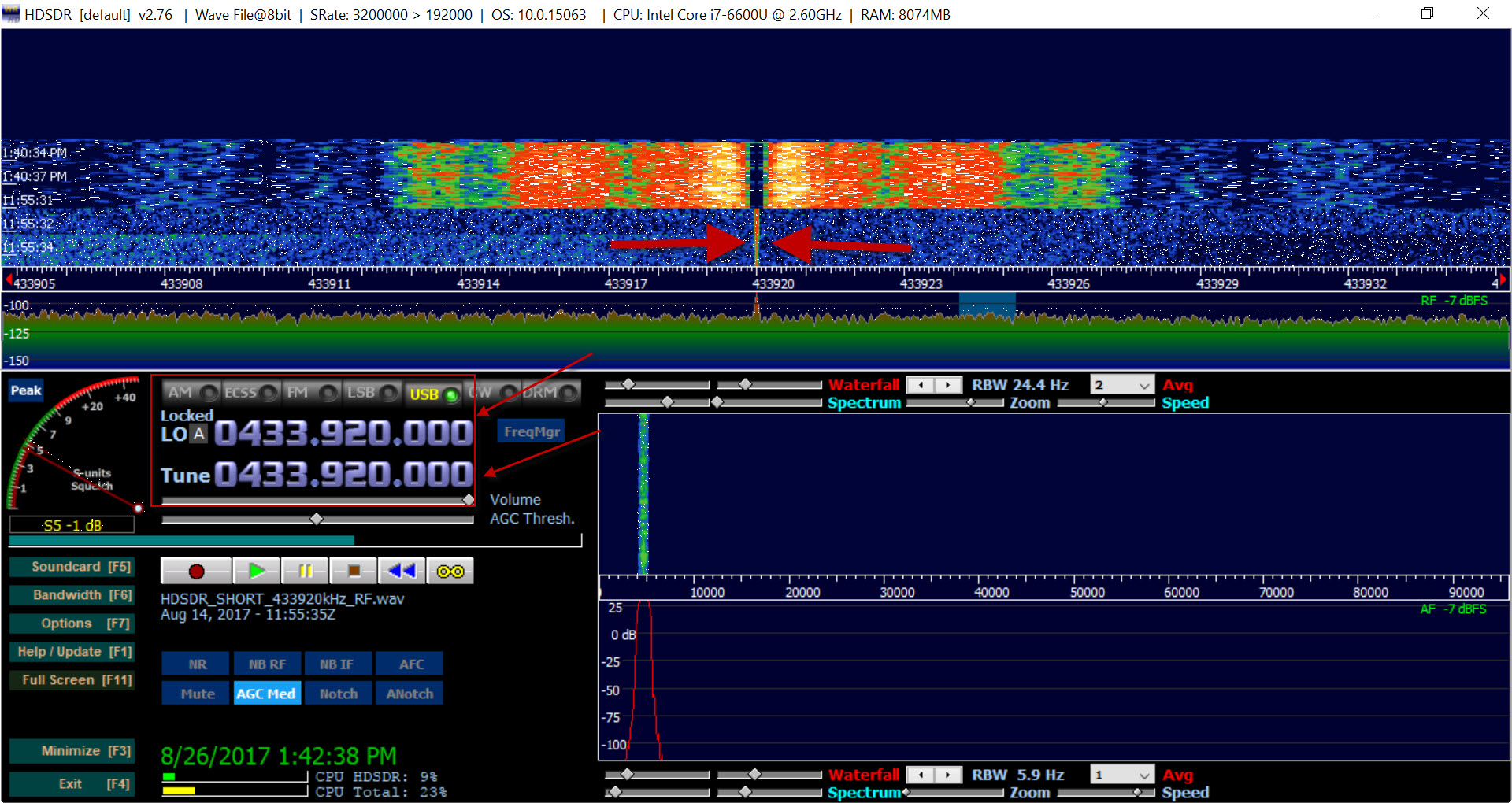
Step 2: tune the correct center frequency and bandwidth
A good thing about garage door openers is that their transmission frequency is regulated. This means you can easily google which one is available in your country. In Spain, most of the openers work in 433MHz. If there are a couple of transmission frequencies in your country and your dongle can use both, all that you need to do it’s tuning the HDSDR to receive in both and see which one works.

If you are not sure what the bandwidth of your signal is, don’t worry: select a high enough bandwidth. Then, while you are receiving the signal, you can see its spectrum and adjust the bandwidth with the cursors:

Step 3: record your signal
Once everything is setup, you can click on the record button of the HDSR software and start pressing your door opener button. You’ll listen many beeps each time you press the door opener, this is right because there are many pulses transmitted.
A cool thing is that this signal can be received from a reasonable long distance (about 40 meters!). Actually, I was sitting in the living room and receiving the neighbor’s garage door opener signal when he was going in! 😊
Your signal will be saved as a .wav file, and by default, this means you’ll get the I and Q components in the time domain (which is pretty cool to be able to process it).
Step 4: process your recorded signal in Matlab to extract the information
First thing to notice is that the signal recorded is a baseband signal. To show that, have a look at the IQ spectrum:

Therefore, there is a 0Hz component is the DC component.
If you are using Matlab, you can load your .wav file and plot it. As you may have recorded a bit of “silence (i.e., noise)” at the beginning of your recording before you press the opener, and a bit of “silence” at the end, a good way to see where the information falls is by plotting the magnitude of the I or Q component in the time domain. For Matlab, the code and signal used in this article is available for free here.

as you can see, I’ve highlighted the part of the signal which contains the information (you can see a train pulses pattern on that bit).
Now, I can extract those samples, plot the information signal and zoom it to see the signal codification:

Also, I measured that the width of a train pulses sequence is 0.0205 s and the pulse period is 0.0362 s, so I can take the first sequence (remember we are still working with the magnitude of the I-component, so an equivalent analysis can be done for the Q-component).

Now, after researching a bit how to deal with these type of signals, here and here I found some interesting information:
- One pulses train is about 200 µs
- Most of the codes can be binary (states 0 and 1) or trinary (states, 0, 1, F)
So let’s zoom a bit our signal to see what happens in the first 200 µs:

As you can see, at the end of the signal, there is a different bit which can be the sync signal to start the next pulses train.
Also, it looks like we have a trinary code with positive (state 1: -3dB), negative (state 0: -43dB) and float (state F: -23dB). You can see this clearly if we zoom in even more:

Note that although the pulses are not fully squared, we can identify the levels as they all keep a consistent amplitude.
Step 5. generating your own garage door opener signal
Now, we can recover the signal by applying a zero-crossing detection algorithm and defining each level. For example, the previous signal zoom after recovering will look like this:

In order to reproduce the complete signal, you can apply the zero-crossing detection algorithm over the complete I component. Then, do it over the Q component and do I+jQ. Once you’ve done this, you can save it as a .txt file in Matlab. This file should be able to be reproduced in most signal generators.
We hope you like this post 😊
Related Posts


About The Author
behindthesciences
We are two engineers who work in the Electronic and Telecommunication industry. We regularly blog in our spare time.