
How to Build a Simple Thermistor Circuit
This tutorial post is on how to build a simple thermistor circuit. There is a variety of temperature sensors on the market all of which meet specific application needs. The most common sensors are the thermocouple, Resistive Temperature Detector (RTD) thermistor. This post focuses on a simple circuit that uses Negative Temperature Coefficient (NTC) thermistors. The Thermistor has a non-linear resistance change-over temperature but since this post only concentrate on using the thermistor to detect only one preset temperature as opposed to using it to measure various temperatures, the non-linearity is not an issue.
The thermistor is connected to the connector J1 in the schematic. Since the non-inverting input of U1:A is connected to ground, a virtual ground is formed on the inverting input of U1:A.
Figure 2: 10k NTC thermistor resistance vs temperature. (From Maxim).
U1:B is configured as a comparator and the reference voltage is determined by a potential divider consisting of R3 and R4.
With the values shown in schematic for R3 and R4, the voltage reference is set at 7.5V. Anytime the resistance of the thermistor Rthem drops below 5k, the output of U1:B will go high, switching the MosFET on. In our case, the MOSFET is driving a Fan.
A value of 5k and lower corresponds to temperature greater than 30 oC.
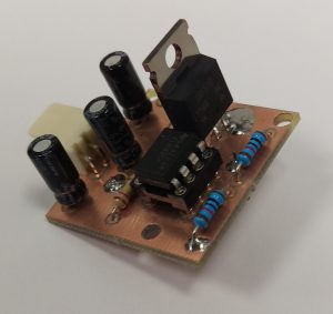
We made the PCB on our in-house PCB milling machine; see video below. A video showing the circuit in action is also shown below. We used a hot air gun to raise the temperature of the thermistor and the fan came on as we designed it.
Related Posts


About The Author
behindthesciences
We are two engineers who work in the Electronic and Telecommunication industry. We regularly blog in our spare time.
