
Connecting an LCD to a Raspberry Pi

A character LCD display can be a good way to visually output information from your Raspberry Pi. 16×2 alphanumeric LCD modules are cheap and there are loads of different type to choose from on eBay with different coloured backlights. Most of the 16×2 modules available on eBay are compatible with the Hitachi HD44780 LCD controller and it means that it is going to work (hopefully!) in the same way as any other. The LCD modules have 16 connections but they are easy to interface to the Raspberry Pi, requiring only 6 GPIO pins on your Pi in “4 bit” mode. Usually the HD44780 requires 8 data lines to provide data to Bits 0-7. However in the “4 bit” mode, only 4 data lines is required, allowing data to be sent in two chunks of 4 bits. This post focuses on connecting an LCD to a Raspberry Pi and controlling it with Python.
For this post, we bought a 1602 16×2 Character LCD Display Module HD44780 Controller Blue Blacklight from eBay for only £1.17!
LCD connections
We used a Raspberry Pi B+ V1.2 and the connections between the LCD and the Pi are as follows:
| LCD Pin | Function | Pi Pin |
| 1 | GND | GND |
| 2 | +5V | +5V |
| 3 | Vo (Contrast) | GND |
| 4 | RS | GPIO-14 |
| 5 | RW | GND |
| 6 | Enable | GPIO-18 |
| 7 | D0 | Not in Use |
| 8 | D1 | Not in Use |
| 9 | D2 | Not in Use |
| 10 | D3 | Not in Use |
| 11 | D4 | GPIO-24 |
| 12 | D5 | GPIO-23 |
| 13 | D6 | GPIO-8 |
| 14 | D7 | GPIO-25 |
| 15 | +5V (Backlight) | +5V |
| 16 | GND(Backlight) | GND |
A schematic showing how to connect your LCD to a Raspberry Pi is also presented below:

Python Script
There are a range of different code available on GitHub that supports the HD44780 LCD controller. Some online forum posts suggest that the Adafruit LCD library can also be used with third-party HD44780 LCD controllers. A good article can also be found at Raspberry-Spy where the author has written his code from scratch. So we decided to use bits of Adafruit code, the data command from the HD44780 datasheet and Raspberry-Spy code to write our own.
#!/usr/bin/python
#--------------------------------------
# 16x2 LCD Rasbperry Pi Test Script
#
# Author : BehindTheSciences
# Date : 14/02/2017
#
# https://behindthesciences.com
#
#--------------------------------------
#import
import RPi.GPIO as GPIO
GPIO.setmode(GPIO.BCM)
GPIO.setwarnings(False)
import time
from BTSLCDPi import BTSLCD
LCD_LINE_1 = 1
LCD_LINE_2 = 2
# GPIO to LCD mapping
LCD_RS = 14
LCD_EN = 18
LCD_D4 = 24
LCD_D5 = 23
LCD_D6 = 8
LCD_D7 = 25
#Create LCD class
LCD = BTSLCD(GPIO,LCD_EN,LCD_RS,LCD_D4,LCD_D5,LCD_D6,LCD_D7)
def main():
# Initialise display
LCD.lcd_init()
while True:
# Send some test
LCD.lcd_string("Rasbperry Pi",LCD_LINE_1)
LCD.lcd_string("16x2 LCD Test",LCD_LINE_2)
time.sleep(3) # 3 second delay
# Send some text
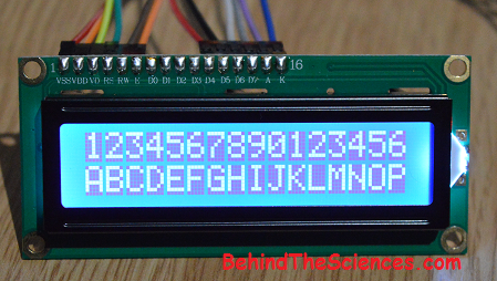
LCD.lcd_string("1234567890123456",LCD_LINE_1)
LCD.lcd_string("abcdefghijklmnop",LCD_LINE_2)
time.sleep(3) # 3 second delay
# Send some text
LCD.lcd_string("BehindTheScience",LCD_LINE_1)
LCD.lcd_string("s.com",LCD_LINE_2)
time.sleep(3)
LCD.lcd_string("1234567890123456",LCD_LINE_1)
LCD.lcd_string("ABCDEFGHIJKLMNOP",LCD_LINE_2)
time.sleep(3) # 3 second delay
time.sleep(3)
if __name__ == '__main__':
try:
main()
except KeyboardInterrupt:
pass
finally:
GPIO.cleanup()
The script can also be downloaded from our Github.
Use the following to run it:
sudo python BTS_LCD_Pi.py
The script was tested with Python 2.7.9. The code presented here was inspired by Raspberry-Spy.
If you use this code with different GPIO pin mapping, make sure to change it in the code. Here are some photos of our working LCD with the Raspberry Pi:


If you have any comments or questions, please email us at [email protected]
Related Posts


About The Author
behindthesciences
We are two engineers who work in the Electronic and Telecommunication industry. We regularly blog in our spare time.

I do the same with you but the back light too high so its hard to see the character, is there any solution to reduced the light ? plz.
Check your LCD pin 3 connection, the contrast pin. You may need to connect a potentiometer between +5V and ground, with the pot wiper connected to LCD pin 3. You can also do the same for the backlight pin instead of to +5V directly. You can then adjust the pot to change the brightness of the backlight and contrast of the characters.
Thanks.
I add a potentiometer between Vo Contrast, Vcc and GND. Its working fun.
Great 🙂